Vision based automatic keystone correction for projectors
As said in my earlier post, I love my BTP and have started working on it. I read a paper today:-
Automatic Keystone Correction for Camera-assisted Presentation Interfaces - Proceedings of International Conference on Multimodal Interfaces, 2000.
Its on keystone correction using camera-projector system.
----------------------
UPDATE : The same author wrote a new version of the above paper 1 year later to be presented in another conference. The new paper explains things better:-
Smarter Presentations: Exploiting Homography in Camera-Projector Systems - Proceedings of International Conference on Computer Vision, 2001.
----------------------
Below are notes on my understanding of the paper.
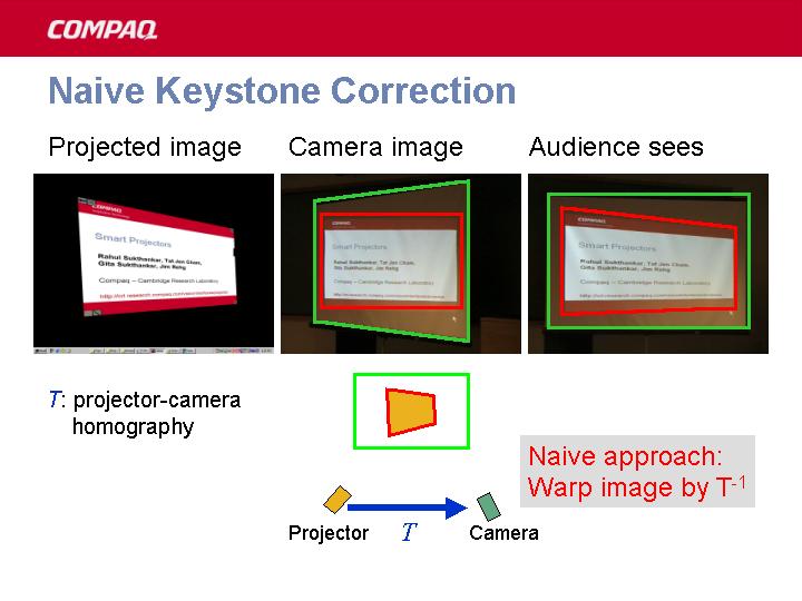
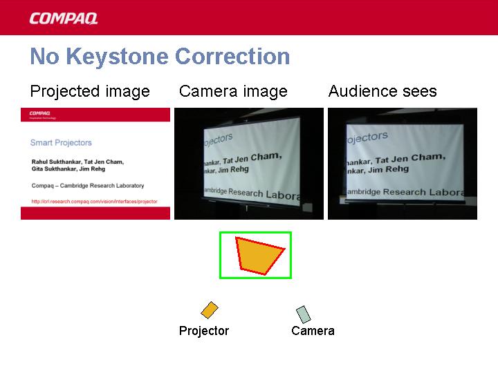
Unless the projector is precisely aligned to the presentation screen, the resulting image suffers from perspective (keystone) distortions requiring manual optical or digital correction. For todays mobile LCD projectors, adjusting them manually every time is a tedious task. This method automates this task using the projector - camera combination.
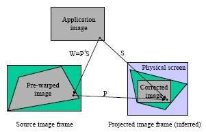
The following three images (courtesy this site) explains this nicely:-
 PS: The notes below are for my personal reference. It may not make sense to you.
Vision Based Keystone Correction
Correcting keystone by pre-warping the image. Uses normal LCD projectors. And low quality(yes very low quality) camera.
Let OrgImg be the orginal Image. ProjImg be the projected image that audience sees and let CamImg is the image seen/recorded by camera.
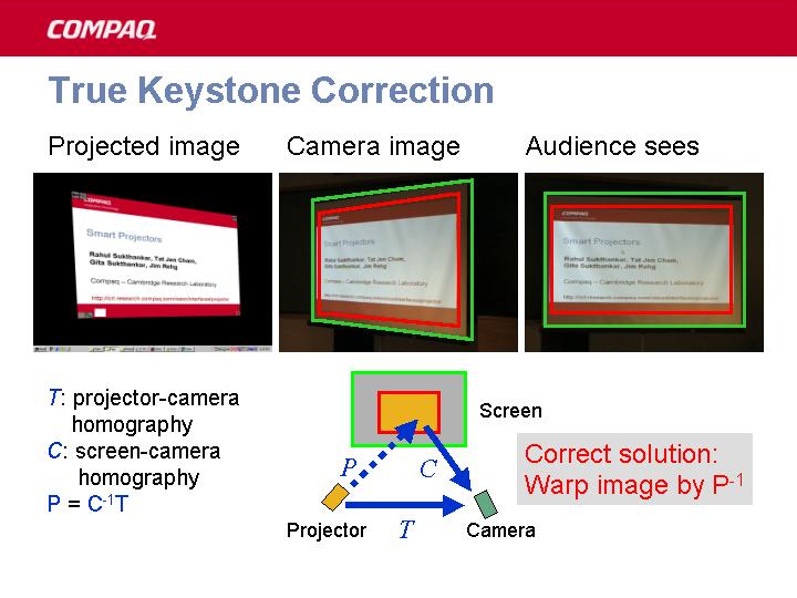
 Now we develop techniques to find the OrgImg -> CamImg transformation (T) and ProjImg -> CamImg Transformation (C). Using these two we determine the OrgImg -> ProjImg transformation (P):-
CamImg = T x OrgImg
CamImg = C x ProjImg
=> C x ProjImg = T x OrgImg
=> ProjImg = C-1 x T x OrgImg
i.e P = C-1T
So to correct the image we just have to apply P-1 to the original image, and apply little scaling and translation (S) to make the image form at proper place and inside the projection keystone.
So W = P-1S needs to be applied.
Calculating T:
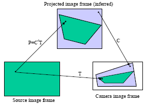
We know that OrgImg to ProjImg (P) is a perspective transform and so is ProjImg to CamImg (C). But the combination of them, that is OrgImg to CamImg (T) is not. We can represent the transformation from OrgImg to CamImg (T) as:-
| (p1X + p2Y + p3) (p4X + p5Y + p6)where (x,y) is a point in OrgImg and (X,Y) is a point in CamImg. ( By the way, reverse mapping can also be represented in the same way. ) There are 9 unknowns. But actually only 8 since p12+p22+...+p92=1. I don't know how that constraint came. I understand that since we are dealing with homogeneous co-ordinates, so there are only 8 unknowns. But how did the author of the paper came with that constraint, I don't know(please comment if you know). So 4 points are enough.(Each point provides 2 equations.)
|(x,y) = ---------------- , ----------------
| (p7X + p8Y + p9) (p7X + p8Y + p9)
This transformation can be represented as a matrix (T) (using 2-D homogeneous co-ordinates):
| - -These unknowns are found using 4 points on the screen during the setup of projector(using some predefined image).
|T=| p1 p2 p3 |
| | p4 p5 p6 |
| | p7 p8 p9 |
| - -
Calculating C:
The four corners of screen is used to calculate this in a similar manner as done above.
The picture below explains the result:-
 I will be posting more on this as I read more. Got to give a presentation on applications of camera - projector systems.

1 comment:
This is a very interesting paper! I too am trying to understand the procedure in detail. But I can't imagine that the 9th equation on the p's should be correct, since for small transformations the matrix should be close to the identity matrix, in which case the sum should be 3, not 1 (p1=p5=p9=1, others=0).
Post a Comment