How about a projector which does not need a white canvas or a flat surface to project on?
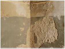
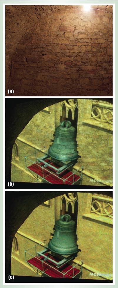
I was reading about my BTP(Smart Camera - Projector Systems), and then found this cool application of it. No need to roll down a big white canvas anymore for a theater experience. Just select any part of your wall, or just a curtain, a table cloth or just anything. The surface need not be even flat..., you can even choose corners of your room as a screen..... To know what I am talking about see the pics below:-
A scruffy corner(yes a corner of a wall!):- Output of a normal projector(notice the effect of choosing a corner as your viewing screen):- Geometry-Corrected output by the smart camera-projector system: Geo+color corrected output by smart camera-projector system:
For more read this or this research paper(pdf). Here a few more cool pics:- Projection on a natural stone wall inside a castle vault (click to get a larger view):- Projection on a checkered curtain:-
I read one more paper today by the same author. This paper is an advancement of his earlier paper on shadow elimination. The new technique not only eliminates shadows but also removes the light falling on the occluder i.e. the person presenting the slides. This prevents the presenter of the annoying bright light falling on his/her face.
The logic is an advanced version of the one used in simple shadow elimination, explained in my earlier post. The shadow elimination part is same. But now we need to identify which projector's light is being blocked by the presenter and turn off the blocked pixels of that projector. For that the author uses a cyclic check. The author defines a new alpha this time, which is not the same for the corresponding pixels of all the projectors. Its different for each of the projectors. dajt = (dajt)SE + (dajt)LS, where d stands for the triangle - symbol for delta and a stands for alpha. SE is shadow elimination and LS is light suppression. Delta alpha jt SE is the same old alpha of last post. (dajt)SE = - y(Zt - Zo), where y stands for gamma which was choosen as 0.25 by the author. This shadow elimination alpha is same as before. The new thing is:- (dajt)LS = - B(da2j(t-N))/(dZ2(t-N)+e), where B stands for a beta(a constant) and e for epsilon just added to prevent the denominator from being 0. Now if changing the alpha valus of projector j does not change Z i.e. dZ is 0, then that projector is being occluded and its alpha should go to 0. so when dZ goes 0, denominator becomes very low, so the overall fraction becomes very high and the minus sign leads to subtractiion which makes the alpha near to 0. So thats how Light suppression works. LS has to be done in a cyclic way. Changing alpha LS for the projectors one at a time. For 2 projectors its pretty easy. Now the author clips dajt = (dajt)SE + (dajt)LS, to between 1 and 0 to prevent it from going out of bound.
Yes I am posting very frequently nowadays. The reason is I am reading a lot of papers for my BTP. I have to give a presentation soon on Applications of Smart Camera-Projector Systems. A lot of cool things could be developed by combining a camera and a projector. I have already blogged about Keystone Correction and Presentaion Control using Laser Pointer. Today I am writing my notes on what I understood about Shadow Elimination using 2 or more projectors by reading this paper:- Dynamic Shadow Elimination for Multi-Projector Displays - Compaq Tech Report CRLTR 2001/4. This video(courtesy this site) explains the concept nicely:-
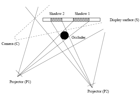
A major problem with interactive displays based on front-projection is that users cast undesirable shadows on the display surface. This situation is only partially-addressed by mounting a single projector at an extreme angle and pre-warping the projected image to undo keystoning distortions. But shadows can be muted by redundantly illuminating the display surface using multiple projectors, all mounted at different locations, and with the aid of a low resolution camera. The camera could be mounted at extreme angle to the screen.
This task is done in three steps:- 1. Automatic Multi-Projector alignment: First of all, all the projectors need to be aligned accurately so that they don't form multiple images on the screen (note that 2 projectors are enough for dynamic shadow elimination). For this, the transform for each projector to camera has to be determined. A few reference images are first displayed and their images are taken by camera. Using these, the transforms for each projector is determined by the method described in my earlier post on keystone correction. Note that, in keystone correction, there was only 1 projector. But here we have to align more than 1. For this the scaling+translation matrix S is choosen appropriately.
2. Occlusion detection: Note that we can only remove penumbral shadows. Umbral shadows i.e. the shadows formed when light from no projector is reaching at a spot could not be removed. Also note that a single occlusion can cause multiple shadows because we have multiple source of lights(projectors).
The technique used is very simple - negative feedback. First a reference image is created for each slide. For this, each slide is presented and camera takes a few images of it. This is done as an intialization step and no occlusion should be present during this process. Note that this is kind of bad. Before each presentation, the system will create reference images of all the slides, which may take around may be 1 mintue. Also this technique will work only for static slides. Won't work for slides containing animations or videos. I think this concept of reference image is the only glitch in this whole technique of shadow elimination. So after the initialization step is over, user can start the presentation any time. The camera takes images and calculates the pixel by pixel difference of the current image and its corresponding reference image taken earlier i.e. It(x,y) - I0(x,y). The difference come out to be negative for pixels correspondig to shadow regions and almost 0 for normal regions. The system then adjust the intensities for the new time step as:- Alpha is the intensity multiplication factor(0-255). Intially it is set at 256/(no. of projectors). For a 2 projector system, this is 128. Then this alpha is adjusted everytime based on the difference image - negative feedback. Note that this alpha is calculated for all the pixels. For a 2 projector system the value of alpha will change gradually from 128 to 256 for the pixles corresponding to the shadow regions. This perfectly eliminates the shadows. Note that the same alpha is valid for all the projectors and need not be calculated separately for each one. This is because the increase in alpha of the projector being occluded has no effect on the slide, because that projector is already occluded! The paper author used a value of 0.25 for gamma. He claims this leads to stabilization in around 3 steps for his experiments. 3. Shadow elimination: Now this alpha mask i.e the set of pixel differences calculated above needs to be applied to all the projectors. But we calculated this mask in camera frame/domain. We transform this in the original domain using the inverse of T, calculation of which I explained in my Keystone correction post. Now apply this mask and bingo! shadow is eliminated!
Next I am reading a paper from the same author on Dynamic Shadow Elimination with Occluder light suppression. Note that when a presenter comes in front of a projector, not only he casts a shadow but he/she is also annoyed with the bright light falling on his/her eyes. Occluder light suppression algorithm identifies which projector is being occluded and its corresponding pixels are turned off. So no light falls on the presentor and the shadow is still eliminated using the help of other projector(s). Note that the projector as a whole is not turned off but only the pixels that are under the shadow are turned off. Watch this video to see it in action(courtesy this site):
I am not quite impressed with the results in above video. I would prefer simple shadow elimination without the occluded light suppression because the annoying to the presenter is not that important as compared to the artifacts that we see in the above video.
Vision-based Presentation Control is another small application for smart camera - projector systems.
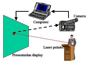
Vision-based presentation control frees the speaker from standing beside the computer while delivering a talk. The speaker uses a pointing device (typically a laser pointer) to activate virtual buttons on the projected slide to drive the presentation.
This one actually uses the same concept being used by the keystone correction that I talked about in my earlier post. In fact, its much simpler. Just detect the position of the laser pointer in the camera Image CamImg and map it to the original image OrgImg using the inverse of transformation T (discussed in my earlier post). Thats it. Once you know the position of laser pointer in the original image, check if its on some button or not and do appropriate actions. The vision part is this much only. Rest is software, provide different kind of buttons and all. The author of the paper from where I read this has provided a few extra buttons that makes it easier to go to next and previous slide.
---------------------- UPDATE : The same author wrote a new version of the above paper 1 year later to be presented in another conference. The new paper explains things better:- Smarter Presentations: Exploiting Homography in Camera-Projector Systems - Proceedings of International Conference on Computer Vision, 2001. ----------------------
Below are notes on my understanding of the paper.
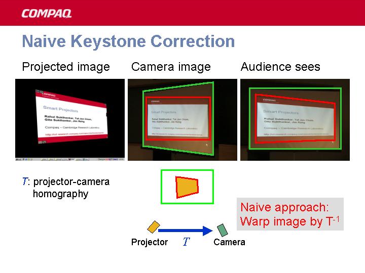
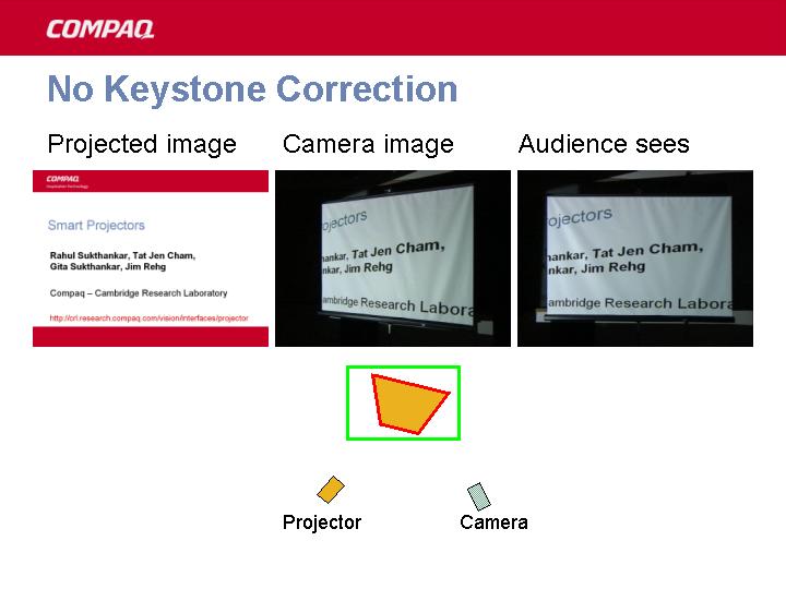
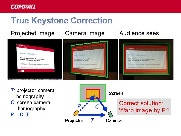
Unless the projector is precisely aligned to the presentation screen, the resulting image suffers from perspective (keystone) distortions requiring manual optical or digital correction. For todays mobile LCD projectors, adjusting them manually every time is a tedious task. This method automates this task using the projector - camera combination.
The following three images (courtesy this site) explains this nicely:- PS: The notes below are for my personal reference. It may not make sense to you.
Vision Based Keystone Correction Correcting keystone by pre-warping the image. Uses normal LCD projectors. And low quality(yes very low quality) camera.
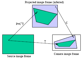
Let OrgImg be the orginal Image. ProjImg be the projected image that audience sees and let CamImg is the image seen/recorded by camera. Now we develop techniques to find the OrgImg -> CamImg transformation (T) and ProjImg -> CamImg Transformation (C). Using these two we determine the OrgImg -> ProjImg transformation (P):- CamImg = T x OrgImg CamImg = C x ProjImg => C x ProjImg = T x OrgImg => ProjImg = C-1 x T x OrgImg i.e P = C-1T
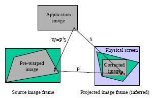
So to correct the image we just have to apply P-1 to the original image, and apply little scaling and translation (S) to make the image form at proper place and inside the projection keystone. So W = P-1S needs to be applied.
Calculating T: We know that OrgImg to ProjImg (P) is a perspective transform and so is ProjImg to CamImg (C). But the combination of them, that is OrgImg to CamImg (T) is not. We can represent the transformation from OrgImg to CamImg (T) as:-
where (x,y) is a point in OrgImg and (X,Y) is a point in CamImg. ( By the way, reverse mapping can also be represented in the same way. ) There are 9 unknowns. But actually only 8 since p12+p22+...+p92=1. I don't know how that constraint came. I understand that since we are dealing with homogeneous co-ordinates, so there are only 8 unknowns. But how did the author of the paper came with that constraint, I don't know(please comment if you know). So 4 points are enough.(Each point provides 2 equations.) This transformation can be represented as a matrix (T) (using 2-D homogeneous co-ordinates):
These unknowns are found using 4 points on the screen during the setup of projector(using some predefined image). Calculating C: The four corners of screen is used to calculate this in a similar manner as done above.
The picture below explains the result:- I will be posting more on this as I read more. Got to give a presentation on applications of camera - projector systems.
Yesterday I got my BTP under Prof. X inspite of doing absolutely nothing on the hons. project under him for the whole of 5th semester. There were reasons for not working. The combination of me and my partner was not right. Moreover, neither of us was actually interested in the project that we got - SBD. So we ended up doing nothing for the whole sem. But I am very grateful to Prof. X that inspite of all this he believed in us and alloted us BTPs. And yes we have now taken BTPs separately. Hope this concept of single would work out right.
And yes the BTP that I have got is really cool. It is to explore the various possible applications of Smart Camera - Projector systems and build and demonstrate a few of them. One of the possible cool applications could be: Project the image of a piano on a table. And press those virtual 'projected keys'. The attached camera will track your hand movements and instruct the computer to produce the corresponding sounds and tones. Cool... isn't it? No need to take a 2 m long 50 Kg bulky piano with you. Just take a 6x3x2 inch camera+projector system, attach it to ur laptop and releash the pianist inside you.... at home, on train, on flight, at picnic!!. And yes todays LCD projector + camera systems are of such small dimensions. And mind you THEY ARE POWERFUL.
I really like this project and won't disappoint Prof. X again.